|
|
|
|
Phase 1: Project Goals Progressive Meshing offers good potential as an automatic LOD generation algorithm. It may be a good terrain continuous LOD algorithm, but this is disputed by some. Though the concentration in this project was on PLY models (Stanford Bunny), I also ran some terrains through it for basic interest, but View Dependent Progressive Meshing is probably a better choice for terrains. The goal of this project was to develop a program that would perform the pre-computation of the progressive mesh for a given object (PLY file or DEM file) then would write it out to a file which could be read by a viewer. As part of this project, a viewer was also developed.
Progressive Meshing To simplify and increase the performance of final display, the decision was made to not permit collapsing to a new vertex. Instead an edge must collapse to one of its existing vertices. This limits the vertex list required for display to the original set of vertices and nothing more.
High Polygon Data
Quadric Error Metric This implementation does not take into account color, texture, etc and therefore does not try to minimize the effects in these domains. Papers have been published extending this technique to address these, and I may add support for these extensions at a later date.
Mesh Generation Implementation
Viewer Implementation Though the speed of collapses and splits is extremely fast, the viewer could be optimized to improve the rendering speed. All of the triangles are rendered via looking up their vertices in the vertex list. The vertex list is not optimized for best cache utilization, which could easily be done in either the file writer or in the file loader. No work has been done yet to optimize this final rendering (because it isn't that slow.)
Illustrating The Usage of Levels of Detail on Polygon Models
|
676 polygons.
1841 polygons.
4171 polygons.
10k polygons.
65k polygons.
|

|
|
|
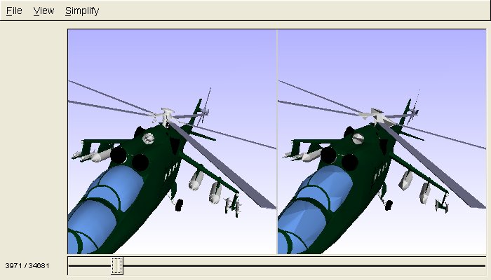
Terrain Progressive meshing does lend itself to terrains, though typically by using the View dependent version of the algorithm. As part of the project, the view independent algorithm developed here was applied to terrain cells read from DEM files, mostly for testing purposes. The image to the right shows a 125,000 polygon terrain cell meshed down to 62k, 1751, and 516 polygons. Each quadrant in the image is a different level of meshing. The display is wireframe for each quadrant, even though the 125k quadrant appears so dense it looks to be solid shaded.
|
|
|
Boundary Handling Boundary handling is an important topic in that just about every model has some level of boundary which may or may not be important. In the case of the bunny, it has four holes in the bottom of the model. (See images to the right.) My implementation of the progressive meshing allows the user to specify whether the algorithm can collapse along a boundary (both verts are on the boundary) or collapse the boundary into the model (where only one of the verts is on the boundary.) The former allows it to simplify the boundary without losing the general shape. The later allows the algorithm to save polygons, if need be, by changing the entire shape of the boundary. Typically the latter is not enabled, where as the former is by default enabled. If the boundary is extremely important and must match its original definition (an example would be terrain cells where they may be required match vertex-for-vertex at the borders), both settings can be turned off. This will force the algorithm to use more polygons for representing the border, at the cost of the rest of the model.
Performance Improvements Finally, storing the faces in a vector was replaced with using a set. Due to the number of times that faces were being added and removed, the STL vector was causing some slow downs. After all the work, Bunny is now decimated from 65k polygons to 16 polygons in approximately 8 seconds. Computing the mesh is a pre-processing task, so 8 seconds is plenty fast enough.
Summary
|

Boundaries on 65k polygon version.
Boundaries on 1k polygon version.
For those people who wonder what bunny looks like at 99 polygons! |
|
Phase 2: General Purpose Implementation The goal of phase 2 of this project was to develop a more general purpose implementation of the above Progressive Meshing work. This included the ability to load various model files, to handle material attributes in the model, and to then develop a plug-in which could work in the Carbon Graphics GEO modeling application.
Basic Application Next, the Progressive Meshing algorithm was refactored to be more robust, to catch more error scenarios, and to better recover from error scenarios. It was then adapted to support operating on the scene graph representation. |
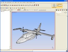
 The Application showing a 3D studio model loaded, and simplified to about 10% of its original polygon count. |
|
Material Handling
|
 Configurable Attribute Weighting.
|
|
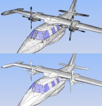
GEO Plugin The final stage of the project was to adapt the algorithm and components to work within the Carbon Graphics GEO plug-in development environment. When the algorithm was refactored to operate on a scene graph, the algorithm was actually modified to use a generic bridge structure for working with the scene graph (for loading model data and simplification of the model). Therefore, making the changes to support the Carbon Graphics scene graph structure simply involved developing a bridge interface for their scene graph. The Basic Application and its configuration dialogs use FLTK like Carbon Graphics, so most of the GUI components could also be used. This left developing the tool bar GUI that plug-ins have in GEO. This is a small GUI which mostly includes the slider for the real-time simplification display, and the ok/cancel buttons. Under the hood, support for generating Undo data (about the simplification) had to be added. The GEO plug-in did bring one more feature which did exist in previous versions. The ability to specify generating a Level of Detail. The user can real-time adjust the model resolution, then click "LOD" which will generate a level of detail for the current selection. The user can then adjust the resolution again, and generate another LOD. This allows a user to quickly take a full resolution model, and generate 4 levels of detail in one simplification process! It works extremely well and is very fast. Finally, GEO supports scripting so a GEOScript interface was put on the plug-in which allows a user to build scripts for performance simplification.
|
 The GEO Simplify plug-in started and ready to simplify.
|


|
Nintendo DS Progressive Mesh Viewer The progressive mesh generation toolkit developed in the above phases of the project supports outputting an optimized viewer file. The viewer library simply needs to modify the triangle indices to increase or decrease the output triangle count, and therefore the model resolution. The viewer was ported to the Nintendo DS for investigation into the DS rendering capability. The screen shots to the right are from one of the NDS emulator. One screen shows the 3D render and the other shows console output for the current resolution level. |

|

|
|
|
||